

4 Inch Column Still Plans, Version 6A
This 4" column still is a compilation of both existing still knowledge and experimentation with combinations of ideas taken from different stills and combinations of material sizes to create a home fuel still capable of producing at least 5 gallons per hour of 190+ proof alcohols.
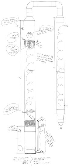
This Don Franson Column Still Design is Available Here on this webpage and in Downloadable .pdf Format Through This Link
Volume of output from a column still is dependent on volume of input, and input is dependent on the opening for the vapor to enter the still.
Maximum output can be achieved by attaching the column directly to the top of the boiler, however due to the practicality I have incorporated a 1 inch vapor input leading into an appropriate bubbler.
4" Column Still Plans Parts List
-
 70"
of 4 inch copper pipe
70"
of 4 inch copper pipe - 36" of 3 inch copper pipe
- 4" copper pipe connector
- 4" to 2" copper adaptor
- (2) 3" to 2" copper adaptors
- 2" to 1/2" copper adaptor
- 30" of 2 inch copper pipe
- (2) 2" copper elbows
- 14" of 1" copper pipe
- (2) 1" copper elbows
- 20" of 1/2" copper pipe
- (2) 1/2" X 1/2" X 1/2" copper "T"
- 1/2" copper elbow or 45 degree connector (optional)
- (2) 1/2" copper pipe to 1/2" male thread adaptors
- 1/2" copper pipe to 1/2" female thread adaptor
- 60 feet 3/8" OD soft copper tube
- 60 feet 1/4" OD soft copper tube
- (2) Sillcocks (faucets) suitable for hot water with 1/2" threaded inlet and notched flange for easy mounting.
- 1/2" pipe thread to 3/8" tube adaptor
- 1/2" pipe thread to 1/4" tube adaptor
- 1/4" tube to female hose thread. adaptor
- Garden hose "Y" adaptor
- adaptor from back of valve to 3/8 inch tube
- adaptor from front of valve to female hose thread
- 100 feet copper mesh
- 300 marbles
- 4" stainless steel floor drain cover
- (6) Wood 2 X 4s or other materials to build the frame
* There are several different valves that can be used on this still and each brand has different size connections.
Version 6A Column Still Assembly Plans:
- Measure and cut 1 piece of 4 inch copper pipe 60 inches long and file off the rough edged for safety.
- Mark hole locations on pipe at 7 inches from top and 4 inches from bottom edge and drill 3/8 inch cooling coil holes.
- Measure down 4 inches from top directly over the 3/8 inch hole and drill 7/8 inch hole for the valve probe.
- To the left of the previous holes 1/4 the way around the pipe, measure down 5 1/2 inches from the top and drill a 5/8 inch hole for the thermometer probe.
- Stretch out 50 feet of 3/8 inch OD copper tube and heat it up a few feet at a time with a propane torch till it changes color, this will soften it and make it easier to bend. Bend as much of it as possible around a length of 2 inch pipe covered with a couple of turns of cardboard to form the coil. Expect a little collapse due to the tight coiling but do not let it kink.
- Before inserting the coil into the pipe you will need to expand the coil until the ends match up with the holes, make the coil tighter at the top than the bottom.
- Finally you will need to either wrap it or cover it with 2 layers of copper mesh.
- Insert coil into pipe and one end at a time pull or push coil end through the 3/8 inch holes and attach 3/8 inch pipe connectors to the ends and solder in place.
- Solder threaded 1/2 inch thermometer connector to a length of 1/2 inch pipe and then measure and cut pipe so that thermometer probe will extend well into the 4 inch pipe but not touch the back wall. The 1/2 inch pipe should be cut so that it can be soldered but not extend much longer than 1/4 inch into the 4" pipe.
- Do not solder the thermometer connector in yet, that will be done after marbles and more mesh are installed.
- Just like you did with the thermometer adaptor you will now make an adaptor for the Valve probe. Solder a length of 3/4 inch copper pipe to a threaded adaptor that fits the valve probe threads.
- Measure and cut the 3/4 inch pipe so that the probe protrudes into the 4" pipe but does not touch the back wall and the copper pipe extends about 1/4 inch into the 4" pipe.
- Again do not solder this adaptor into place yet.
- Measure and cut a 10 inch section of 4" pipe and file down the edged to prevent injury.
- Solder an end cap onto the 10 inch section.
- Measure up 3/4 inch from the bottom and drill a 5/8 inch hole though both the end cap and the wall of the 4" pipe.
- Make the low proof outlet and overflow vent: Cut 2 pieces of 1/2 inch pipe 1 1/2 inches long each and solder into the 2 ends of a copper "T".
- Solder a 1/2 inch male pipe thread adaptor to one of the ends.
- Cut and solder an 8 inch piece of 1/2 inch copper pipe into the side of the "T".
- Solder another "T" to the other end of the 8 inch pipe.
- Cut and solder a 2 inch piece of pipe into the side of the "T", this will be the actual low proof outlet and you can either connect a hose to this end with a clamp or you can solder a hose connector here to make connecting and disconnecting a hose easier.
- The top end may be left open or you can dress it up by adding another piece of 1/2 inch pipe and an elbow or 45 degree connector.
- Attach the ball valve to the threaded connector using Teflon tape.
- Do not solder this piece in place yet, you have more holes to drill first.
- 1/4 the way around to the right of the 5/8 inch hole on the 4 inch pipe, measure up 1 3/4 inches from the bottom and cut a 1 1/8 inch hole for the vapor inlet.
- To make the bubbler tube: Cut and split a little over 1 inch of 1/2 inch or larger pipe and flatten out.
- Solder the flat piece of copper to the end of a length of 1 inch copper pipe.
- Cut and file the end piece to make a smooth neat end for the copper pipe.
- Drill a series of 1/4 inch holes into half of the pipe but only out to 3 1/2 inches from the new end you made.
- (This is different from the drawing but an important update) Cut the bubbler pipe to 5 inches in length and solder an elbow to the open end (with the bubble holes facing the same way as the L in the elbow.
- Measure and cut a 9 inch or longer piece of 1 inch pipe and solder to the elbow.
- Measure and cut a 4 or 5 inch piece of 1 inch copper pipe and connect to the 9 inch piece with another elbow, making a "Z" shape out of the entire set of pipes.
- Do not solder this into the bubbler section yet.
- Next you need to make a drain cover to keep the marbles from falling into the bubbler section, this is best done by using a standard stainless steel floor drain cover and grinding it clown to fit inside the connector but not fall into the bubbler.
- You can now solder the connector to the bubbler section and insert the marble trap.
- Line up the vapor inlet hole on the bubbler section with the 3/8 inch water lines on the column and then solder the column to the connector.
- Solder the low proof outlet and the vapor inlet to the bubbler section.
- Drop 300 standard marbles into the center of the coil in the column and shake them to get them all the way down below the coil.
- Feed and lightly pack copper mesh into center of coil until filled to top of coil, this should use up about 60 to 65 feet of the 100 foot coil of mesh.
- Solder the valve probe adaptor and thermometer adaptor in place at the top of the column.
- Solder the 4 inch to 2 inch adaptor to the top of the column.
- Cut 2 pieces of 2 inch pipe to 4 inch lengths, Cut 1 piece of 2 inch pipe to 12 inches long.
- Solder an elbow to each end of the 12 inch piece, making sure that both elbows face the same direction, and then solder a 4 inch piece into the other end of each of the elbows.
- You may solder one end of the 2 inch connector to the 4 inch column or wait until both columns are finished.
- Cut a piece of 3 inch copper pipe to 36 inches long and file the ends to remove burrs.
- Measure 3 inches from both top and bottom of the pipe and drill a 1/4 inch hole at each location.
- Stretch out 50 feet of 1/4 inch OD copper tube and heat it up a few feet at a time with a propane torch till it changes color, this will soften it and make it easier to bend. Bend as much of it as possible around a length of 2 inch pipe covered with a couple of turns of cardboard to form the coil. Expect a little collapse due to the tight coiling but do not let it kink.
- Before inserting the coil into the pipe you will need to expand the coil until the ends match up with the holes, try to make the coils even from top to bottom.
- Just like the larger coil you will need to either -wrap it or cover it with 2 layers of copper mesh.
- Insert coil into pipe and one end at a time pull or push coil end through the 1/4 inch holes and attach 1/4 inch pipe connectors to the ends and solder in place.
- Solder a 3 inch to 2 inch adaptor to each end of the condenser tube.
- Solder a 2 inch to 1/2 inch adaptor to one of the 3 inch to 2 inch adaptors.
- You can either solder a length of pipe to the 1/2 inch adaptor or attach a hose adaptor to facilitate draining the alcohol to a storage tank.
- Position the 2 columns so that the cooling water adaptors are on opposite sides of each other and solder the 2 inch connector to the top of each column.
- Make a frame out of 2x4's or other strong materials to support the still and hold it a foot or more off the ground. I built mine out of 8 foot 2x4's with 4 corner posts and a full top and bottom 12 inches deep and 36 inches wide to support the bulk of the still. I found that I still had to support it against the side of my garage to keep it from tipping over in strong winds, so you might want to consider a larger base.
- Suspend the still from the top of the frame and attach supports to keep the still stable and the 4 inch column straight up and down, use a level to make sure the column is plumb, leveling the 3 inch column is not critical.
- Attach and anchor Valve to the frame on the left front inside of the frame with support strap, pay attention to the directional arrow on the valve so that water will flow the proper direction.
- Attach 3/8 inch pipe adaptor to back of valve.
- Measure and cut enough 3/8 inch copper tube to attach column inlet (top of still) to the valve, Solder the pipe to the connector on the column and then carefully bend the pipe to allow a straight section to attach to valve. Attach other end to valve being careful not to over tighten the connection.
- A board which will hold the drain faucets must be mounted to the frame. Mount the board in a convenient location for draining the hot water from the still; I mounted mine to the front of the stills frame.
- Drill 1 inch holes to allow the faucet adaptors to protrude through the back of the board.
- Measure and cut outlet tubes and solder to their respective connectors. On the 4 inch pipe it is the bottom 3/8 inch connector which is the drain but on the 3" pipe it is the top 1/4 inch connector which is the drain!
- Screw the pipe adaptors into the back of the faucets using Teflon tape to seal the threads.
- Attach the copper tube to the faucet before attaching the faucet to the board; Use Deck screws to attach the faucets to the board to prevent rusting.
- Connect a hose adaptor to the front of the valve using Teflon tap
- Attach "Y" adaptor to the hose adaptor.
- Measure and cut a length of 1/4 inch copper pipe to attach from the cold water inlet of the condenser to the other side of the "Y" adaptor.
- Solder one end of the 1/4 inch pipe to the cold water inlet.
- Attach hose end adaptor to the other end of the 1/4 inch pipe.
- Attach hose end adaptor to the "Y"
This completes the assembly of the still column; you will just need to attach the hoses and water supply to feed the still.
The only place I was able to find large radiator hose to hook up the still to the boiler was a large truck supply store.
4” Column Still FFS: See full size column still schematic drawing